Skip to Content
Digital View
  • Home
  • Products
    • Controller Boards
    • E Ink Solutions
    • Accessories
    • AI @ Display Edge
    • Services
  • CSG
  • Applications
    • AI Enabled Displays
    • Kiosks
    • Embedded Systems
    • Marine
    • Digital Signage Displays
    • Industrial Displays
    • Harsh Environment Displays
    • Transport Displays
    • Medical Displays
  • How to Buy
    • Resellers
    • Contact Sales
  • Support
    • Compliance
    • Contact Support
  • About
  • Blog
  • 0
  • 0
  • Contact
Digital View
  • 0
  • 0
    • Home
    • Products
      • Controller Boards
      • E Ink Solutions
      • Accessories
      • AI @ Display Edge
      • Services
    • CSG
    • Applications
      • AI Enabled Displays
      • Kiosks
      • Embedded Systems
      • Marine
      • Digital Signage Displays
      • Industrial Displays
      • Harsh Environment Displays
      • Transport Displays
      • Medical Displays
    • How to Buy
      • Resellers
      • Contact Sales
    • Support
      • Compliance
      • Contact Support
    • About
    • Blog
  • Contact
  1. Home
  2. LCD Controllers
  3. LS-1920-HDMI
LS-1920-HDMI LCD controller, 4179500xx-3

LS-1920-HDMI
LCD Controller

  • LCD panel resolution up to 1920x1200, 8-Bit, LVDS
  • Input signal: HDMI, up to 1920x1200
  • Compact 70mm x 97mm x 11mm
  • Multi-Panel support, jumper select
  • Panel-matched EDID, selected with the configured panel timing
  • Audio line out
  • USB firmware upgrade
  • MOQs apply

Part number: 4179500xx-3 (xx = revisions)

Jump to Downloads (bottom of page)

LS-1920-HDMI LCD Controller Board

The Digital View LS-1920-HDMI is a compact LCD controller board for volume commercial and industrial display applications. It accepts a single HDMI input and drives single or dual-channel LVDS TFT panels at resolutions up to 1920×1200. This highly integrated controller board drives TFT LCD panels up to 1920x1200 and incorporates Digital View's multi-panel timing support, RS-232 and DDC/CI control, PWM backlight dimming, IR remote support and audio line-out.

An efficient switching power architecture generates the board’s internal voltage rails and helps minimize controller power consumption and thermal load. Selectable 3.3V, 5V and 12V panel power allows the standard board to support a range of LVDS panels. 

Firmware can be updated in the field over USB.

The feature set ensures suitability for many commercial display applications, including kiosks, industrial, medical, digital signage, and corporate AV. A full summary of Digital View LCD controllers can be seen here: LCD Controller Summary.
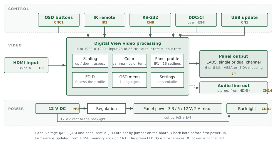
LS-1920-HDMI block diagram. Control comes from OSD buttons on CNC1, an infra-red remote on IR1, RS-232 on CN8, DDC/CI over the HDMI input, and a USB memory stick on CN1 for firmware updates. Video enters as HDMI on P3. Digital View video processing scales the image up to 1920 by 1200, accepts input from 23 to 86 hertz with the output rate equal to the input rate, applies color, gamma and the OSD, and selects one of 16 panel settings by the JP1 jumper. The EDID follows the panel profile. Settings are stored in non-volatile memory. The panel output is single or dual channel LVDS on J3, with VESA or JEIDA mapping. Stereo audio from the HDMI stream leaves on CN14. Power enters at 12 volts DC on PP2. It is regulated to a panel supply of 3.3, 5 or 12 volts, set by jumpers JA3 and JA6 and limited to 2 amps, and passes at 12 volts to the backlight connector CNB1.
LS-1920-HDMI block diagram (click to zoom)

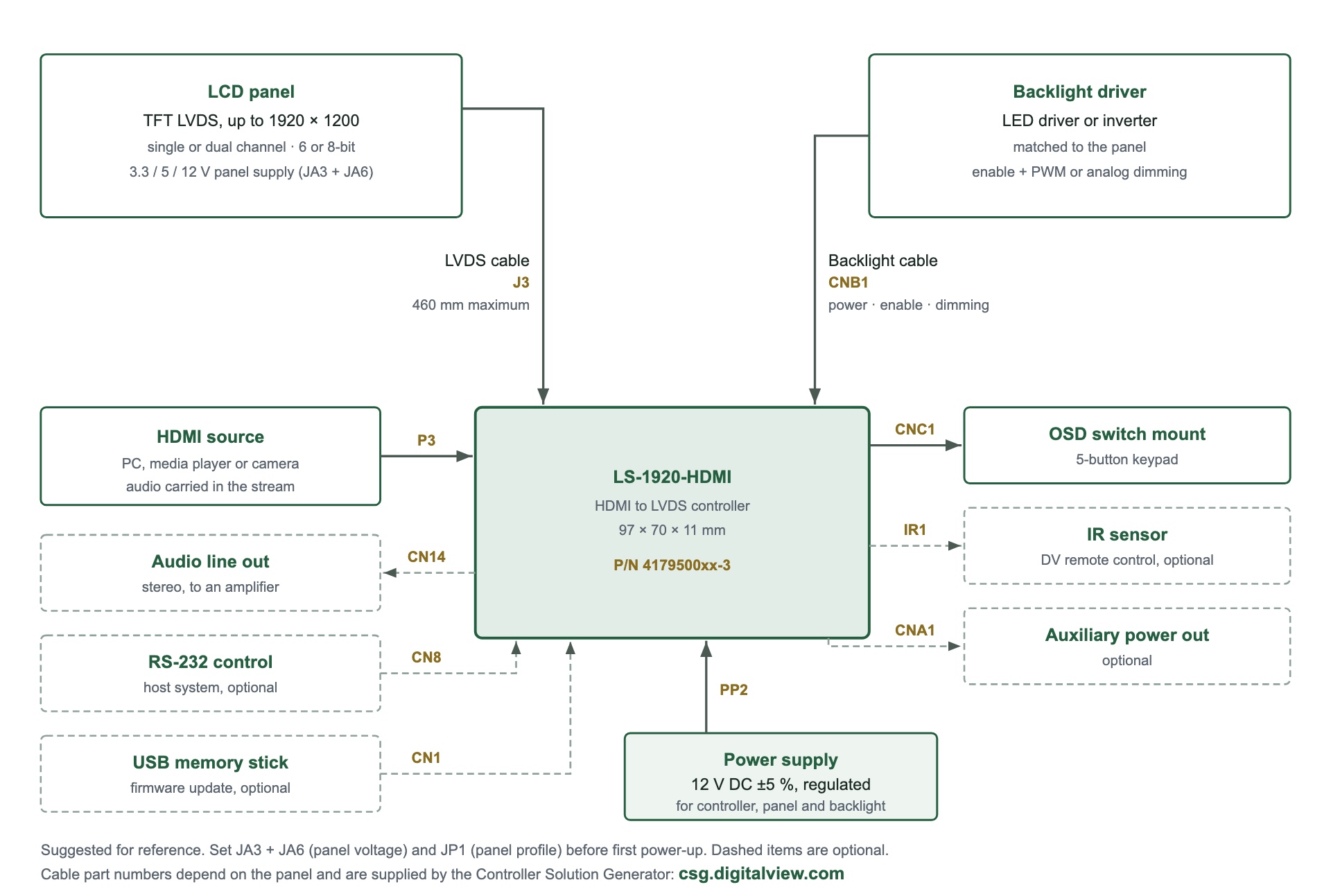
LS-1920-HDMI connection diagram. The controller board sits at the center. The LCD panel connects to J3 by an LVDS cable no longer than 460 millimeters, which also carries the panel supply of 3.3, 5 or 12 volts set by jumpers JA3 and JA6. The backlight driver, matched to the panel, connects to CNB1 for power, enable and dimming. An HDMI source connects to P3. An OSD switch mount connects to CNC1. Optional connections: an IR sensor on IR1, auxiliary power out on CNA1, stereo audio line out on CN14, RS-232 control on CN8, and a USB memory stick on CN1 for firmware updates. A regulated 12 volt DC supply connects to PP2. Cable part numbers depend on the panel and are supplied by the Controller Solution Generator at csg.digitalview.com.

Controller Solution Generator (CSG)
an online database to look up LCD panels and matching controllers

Specifications: LS-1920-HDMI

LCD Panel Connectivity
  • Panel connection: LVDS (single or dual channel)
  • Panel resolutions: Up to 1920x1200, includes standard and custom resolutions
  • Colors: 6 or 8-bit per color
  • LVDS mapping: VESA and/or JEIDA LVDS mapping, configurable via software/hardware
  • Panel timing: JP1 jumper, 16 settings: 12 built-in panel profiles, 4 custom timings uploaded over RS-232
  • Controller power: +12VDC +/-5%, approx. 1.5W (controller logic only, excluding panel and backlight)
  • Panel power: 3.3V, 5V, 12V (jumper selectable), current limited to 2A
  • Backlight inverter/driver support: PWM, Enable pin (3.3V or 5V, jumper selectable)
  • Backlight brightness: PWM control, plus analog brightness VR input
  • Panel Matching & Connection Diagrams: For Connection Diagrams showing setup details for connecting specific LCD panels see the Digital View Controller Solution Generator, click here.
Input: HDMI 2.0 (x1)
  • Input accepted from 23 to 86Hz; output rate equals input rate
  • Interlaced input converted to progressive by line doubling
  • Standard VESA and CTA-861 timings up to 1920x1200
  • Color formats: accepts 8-bit, 10-bit and 12-bit Deep Color at the HDMI input, and drives 6-bit or 8-bit panels. Supports sRGB and xvYCC color spaces
  • HDMI audio: L/R 2-channel PCM audio extracted from the HDMI stream
  • EDID is auto-panel matched and customizable.
Function Interface
  • On-screen display (OSD) menu
  • Buttons (5-button OSD support, momentary buttons) or IR remote control.
  • Serial port (RS-232), Baud rate 9600, 8 bits, 1 stop bit, and no parity, Digital View RS-232 command protocol
  • DDC/CI over the HDMI input
  • USB firmware-update via 4-pin header
Functions
  • Basic: Black level brightness, Contrast, Sharpness, Color temperature, Gamma
  • Other: OSD timeout, OSD position, OSD menu rotation, OSD transparency, OSD menu language.
  • Volume control, Load factory defaults.
Audio
  • Stereo line-output: Single stereo line output connected to audio line out header
  • Output level and impedance: 20mW @ 32 ohm or 40mW @ 16 ohm
  • Volume and mute control: 100-step volume control from the OSD or over RS-232, driving a -60dB to +6dB analog gain stage, with fading/mute
  • External amplifier not required for low-power audio; required for driving > 2W high-power speakers
  • Compatible audio accessory: Onboard 4-pin audio header

Mechanical & Environmental

  • Board dimensions: 97mm x 70mm x 11mm with 5 mounting holes
  • Component height: approx. 7mm above and 2mm below the 1.6mm PCB; board mass 40g
  • Operating temperature: 0 C to +70 C
  • Storage temperature: -40 C to +85 C
  • Operating humidity: 10 % to 90 % RH, non-condensing
  • Storage humidity: 5 % to 95 % RH, non-condensing
  • ESD: HDMI and USB data lines protected to IEC 61000-4-2 Level 4 (±8 kV contact, ±15 kV air). System-level ESD immunity depends on the final enclosure and grounding, and is the responsibility of the integrator.
  • Latency: 11 ms mid-screen, measured with a Leo Bodnar video signal input lag tester at 1920x1080p60
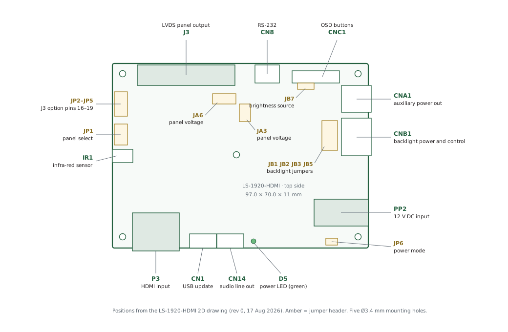
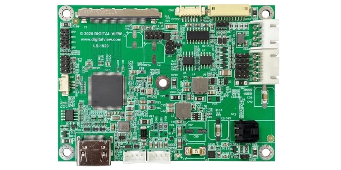
LS-1920-HDMI connector map, top side, drawn to scale at 97 by 70 millimeters. On the top edge, from the left: J3 the LVDS panel output, CN8 for RS-232 control, and CNC1 for the OSD buttons. On the right edge, from the top: CNA1 auxiliary power output, CNB1 backlight power and control, and PP2 the 12 volt DC input. On the bottom edge, from the left: P3 the HDMI input, CN1 for USB firmware update, CN14 stereo audio line out, D5 the green power LED, and the JP6 power-mode jumper. On the left edge: the JP2 to JP5 jumpers for J3 option pins 16 to 19, the JP1 panel-select jumper and IR1 for the infra-red sensor. Inside the board: JA3 and JA6 set the panel voltage, JB7 the brightness source, and JB1, JB2, JB3 and JB5 the backlight options. Five mounting holes, 3.4 millimeters in diameter.
LS-1920-HDMI connectors (click to zoom)

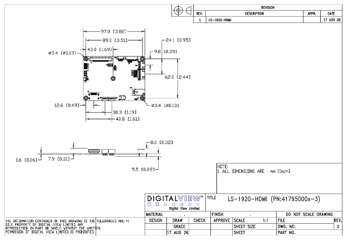
LS-1920-HDMI dimensional drawing. The board is 97.0 by 70.0 millimeters, 11 millimeters deep, with five 3.4 millimeter mounting holes on an 89.0 by 62.0 millimeter span. Connector positions are shown on all four edges.
LS-1920-HDMI dimensions, see downloads

Other
  • EDID: matched to the selected panel, with custom EDID upload. Settings, custom panel timing and the custom EDID are stored in non-volatile memory
  • Audio line out (header) with pre-amp mute control
  • ESD protection on HDMI and USB ports
  • Standby power consumption: approx. 0.6W at 12V
  • Power LED (green)
  • Plug & Play: VESA DDC2B compatible

Reliability


  • MTBF [TBC - to be calculated using Telcordia SR-332 procedure]
  • Warranty 3 years

Customization
(options*)


  • Panel timing
  • Video input timing support
  • Custom EDID
  • Splash screen logo, ie during start-up
  • Build options to omit connectors
  • Full PCBA relayout, conformal coatings & other hardware changes
  • Software utilities or Apps for RS-232 control

Downloads: LS-1920-HDMI

Brochure (PDF)
Manual (PDF)
Revision Note (PDF)
2D Drawing (PDF)
2D Drawing (DWG)
3D Drawing (STEP)

Application Notes

Guide to using RS-232 commands, note that specific RS-232 commands are covered in the controller board manual.

LCD Panel Connection Diagrams

Controller Solution Generator

Software Web Page

Link: Software web page
Includes applications for remote control, settings updates and more.

Statements & Declarations

Statement of volatility — on request
Compliance & declarations page

Related Models


Accessories: LS-1920-HDMI
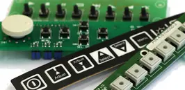
OSD Buttons
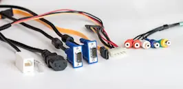
Cables
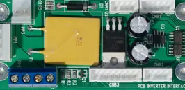
Backlight
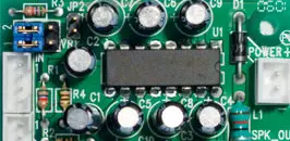
Audio Board
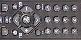
IR Remote

Digital View - enabling digital displays

Digital View, engineering display electronics since 1995. We design and manufacture highly reliable digital display controller boards for LCD, OLED, and E Ink ePaper displays, powering mission-critical applications in harsh environments, medical, industrial, and digital signage. 

Main Pages

Contact Us
Controller Summary
Match LCD Panels & Controller Boards (the CSG)
Office Addresses
Privacy Policy
About

Phone

USA +1-408 782 7773 (Morgan Hill, California)
UK +44(0)20 7631 2150 (London)
HK +852-2861 3615 (Hong Kong)

Follow us

    Contact Us: 

    Sales inquiries or any other questions...

Submit

Cookie Policy

Copyright © 2026 Digital View
Digital View - Enabling Displays

We use cookies to provide you a better user experience on this website. Cookie Policy

Only essentials I agree