EPL-300 Driver for E Ink 75"
- Panel support: E Ink 75" Kaleido
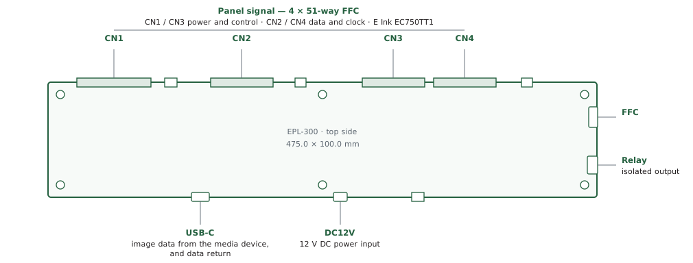
- Inputs: 1 x USB-C
- Panel support: E Ink EC750TT1 (Kaleido)
- Power: 12V DC
Part number
- EPL-300 board: 4160248xx-3
- FFC cables: 426162350-3 (200mm)
Boards for E Ink epaper displays
EPL-300 Driver Board
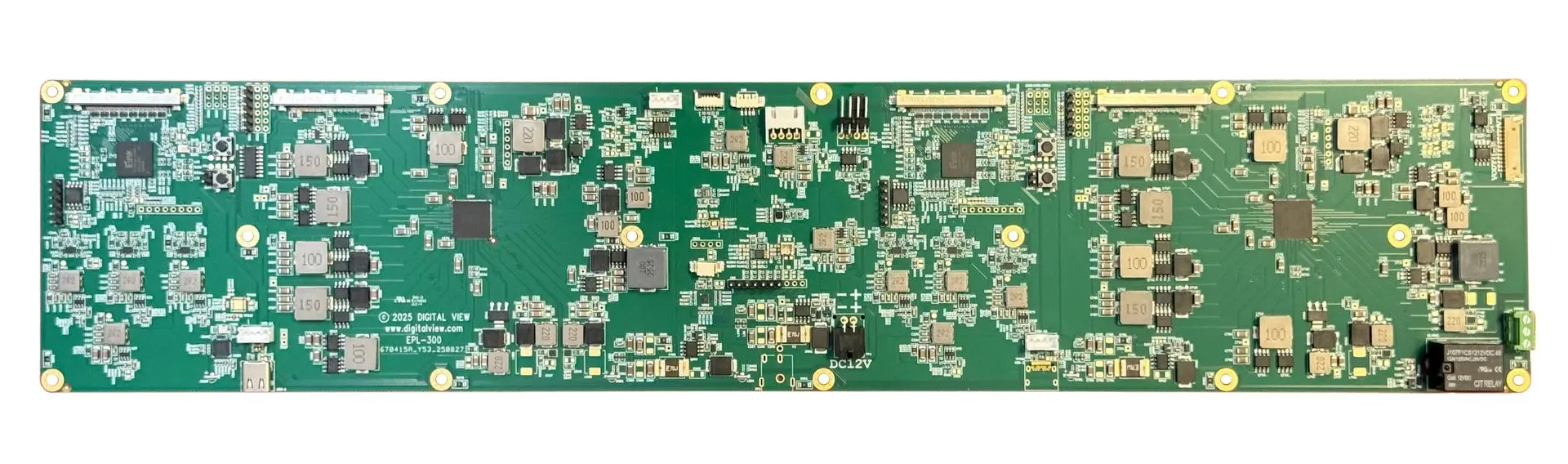
The Digital View EPL-300 is a TCON driver board designed for E Ink 75" epaper display panels. This low-power interface accepts a bitmap image transferred over USB from a source media player such as a Raspberry Pi or Android PC. E Ink based displays are ideal for public signage; the significant benefits include the high visibility in bright environments as well as the ability to operate from solar power due to the very low power consumption.
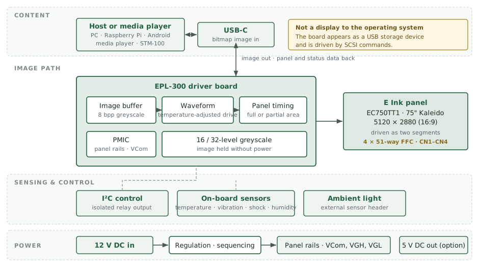
One USB connection, not two. The 75" E Ink panel is driven as two segments, and the E Ink reference design uses a separate USB connection for each. The EPL-300 drives both segments from a single USB-C input, so the host system sees one device with nothing to keep in step — noticeably less software integration work. Two USB inputs are available as an option where a design requires it.
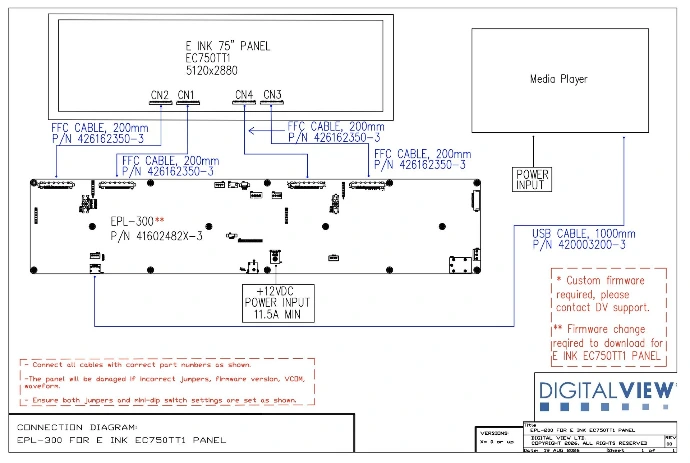
See the connection guide below, after the Specifications
Options: Custom controller board layout with additional functions or integration is available as an engineering service. In addition Digital View can assist with display bonding and other integration requirements for the E Ink panel.
EPL-300 Kit — $495
Driver board, FFC cable, and EP Demo App download. E Ink panel not included. Delivery included within the USA; sales tax added at checkout where applicable.
Controller Solution Generator (CSG)
an online database to look up LCD panels and matching controllers
Specifications: EPL-300
Panel Connectivity
Refer to the appropriate Connection Diagram (PDF)
- E Ink 75" model EC750TT1 (Kaleido)
Resolution
The EPL-300 supports the native resolutions of the E Ink panels
- 75": 5120 x 2880 (16:9 aspect ratio)
Functions
- On-board temperature, vibration, shock, and humidity sensors
- On-board isolated switch for relays for external device power control via I2C control interface
- Header for external ambient light sensor
- 16/32 level grey scale mode
Input
- USB-C x 1 (for image transfer)
Mechanical & Environmental
- Board dimensions: 475.0 mm × 100.0 mm (18.72" × 3.94")
- PCB thickness: 1.6 mm
- Maximum component height: 15.6 mm
- Mounting holes: 3.4 mm diameter, 46 mm + 46 mm vertical spacing — see the 2D drawing
- Panel connectors: 4 × 51-way FFC (CN1–CN4)
- Operating temperature: −15°C to +65°C (panel dependent)
- Storage temperature: −25°C to +70°C
- 2D and 3D drawings: see Downloads & Resources on this page
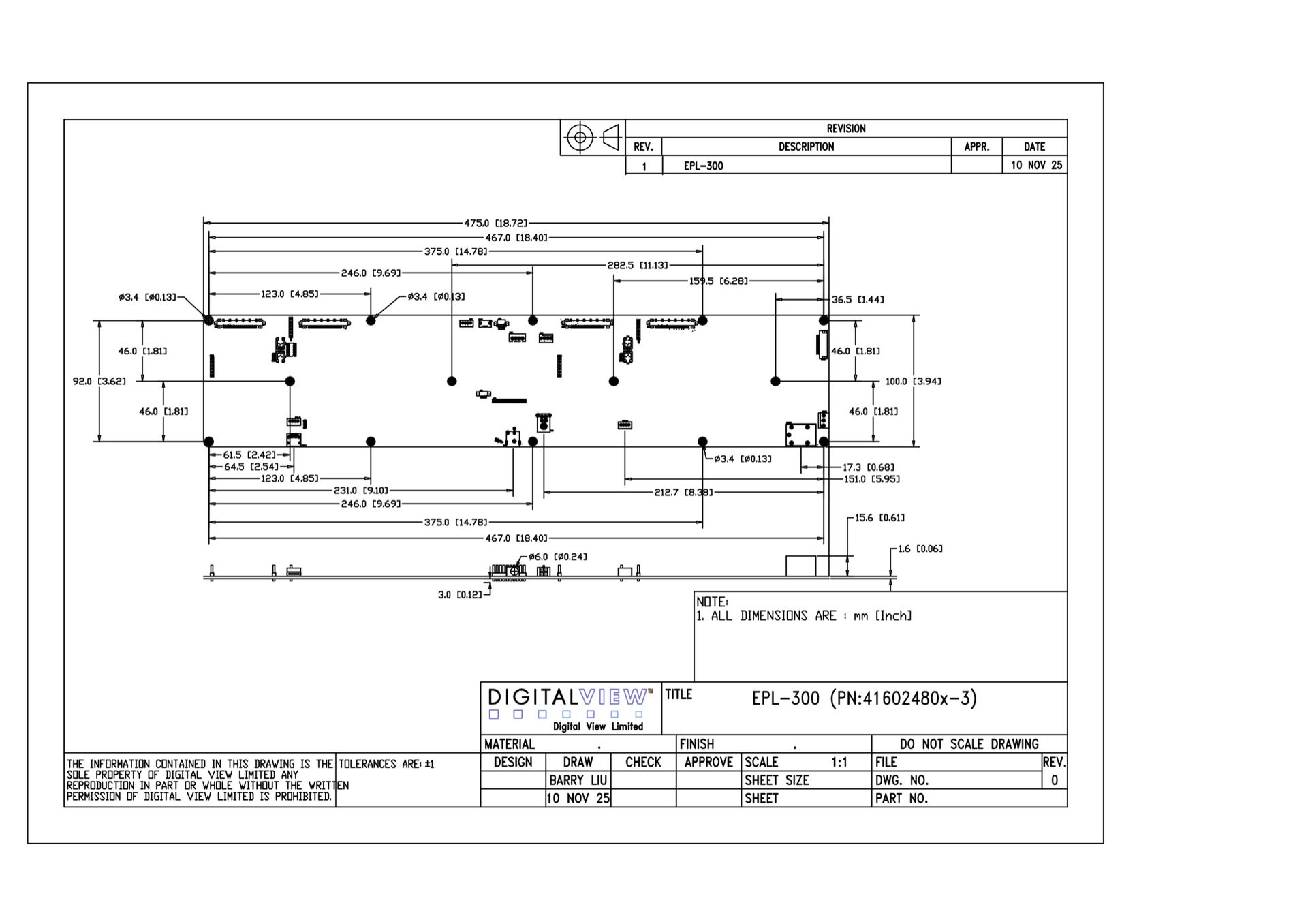
EPL-300 dimensions (click to zoom)
Power
- Power input 12V DC
- Power output (option): 5V DC
Image file
- Supports bitmap (bmp) file format
Operating Temperature
- −15°C to +65°C (panel dependent)
Reliability
- MTBF in excess of 200,000 hours @ 25°C (calculated using Telcordia SR-332 procedure)
- Warranty 1 year
Customization
(options)
- Layout & connector selection
- Conformal coating
*Note: Customization is subject to quote - engineering charges and MOQ may apply.
Downloads EPL-300
Brochure (PDF)
Manual (PDF)
Revision Note (PDF)
Programming Guideline (PDF)
2D Drawing (PDF)
2D Drawing (DWG)
3D Drawing (SLDPRT, STEP)
Application Notes
Panel Connection Diagrams
Controller Solution Generator
Software Web Page
Link: Software web page
Statements & Declarations
Statement of volatility
Compliance & declarations page
Related Models
Frequently asked questions
How the EPL-300 is driven, and what a developer needs to know before starting.
Over the USB-C connection, from your own application. The board is not a display as far as the operating system is concerned — it appears as a USB storage device and is driven by SCSI commands, so there is no monitor for software to output to.
The sequence is four steps: find the device among the attached drives, read its system information, load the image into the buffer, then trigger the panel refresh. Each step is one command, and all of them are documented with sample code in the Programming Guideline.
The USB link is two-way. A single system-information command returns the panel width and height, the address of the image buffer, the number of waveform modes and the number of temperature segments — everything your application needs to size and place an image without hard-coding anything.
You can also read controller memory back, read the mailbox, and poll whether the controller is busy, which is how you know a refresh has finished before sending the next image.
Not on its own. Digital signage software expects to output to a screen, and this board does not present one. In practice you drive it from an application that writes images to it — which can be as simple as a script that picks up a file and sends it.
If your signage system can export images to a folder or call a URL, that is the straightforward route. Talk to us about your setup and we will tell you plainly what is involved.
The reference application supplied with the board is written for Linux and builds with g++. The chip-level programming guide also contains Windows sample code using the standard SCSI pass-through interface, and documents the wrapper Android needs for its bulk-transfer API.
There is no pre-built Windows or Android application today. If that matters to your project, tell us — it affects how we prioritise the work.
A bitmap, with pixels supplied as 8 bits per pixel. Images larger than 60 KB are sent in successive blocks; the reference code handles that for you.
For the color Kaleido panel the image must first be mapped to the panel's color filter array. Ask us for the current mapping tool before you begin — it is the step most people are not expecting.
Yes. E-paper is bistable, so the last image remains readable with the power off and needs no energy to hold it. Power is only consumed while the image is being changed.
That is what makes the technology suited to solar or battery installations, and why an unexpected power cut leaves a readable sign rather than a blank one.
Accessories EPL-300
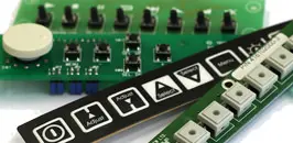
OSD Buttons
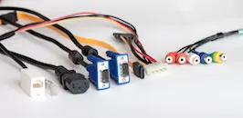
Cables
Front light
Audio Board